Determine the IR drop and heat while the copper can be adjusted
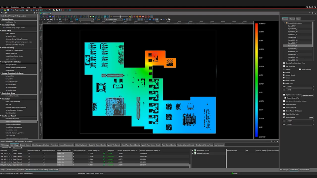
Celsius PowerDC calculates voltage drops, current density, and the heat generated by the current itself—on the board and in the package—directly from the layout, without the need to build models first.
The voltage drop only becomes apparent once the circuit is built
Current density is calculated by hand or not at all
The electrical analysis assumes a constant temperature
Support responses that take days
The solution
We give you control back
IR drop calculated based on the actual layout, not on an estimate
Current density and via load displayed directly on the copper
Current and temperature calculated in the same analysis
Local hotline with responses from a specialist on the same day
HOW IT WORKS
Electricity and heat are linked, and so is the analysis
No models to build first
The layout is imported directly from OrCAD and Allegro or as ODB++ and IPC-2581 files. The first results are available after a brief setup.
Electrical and Thermal in the Same Calculation
Electric current generates heat, heat increases resistance, and resistance changes the current. If you calculate them separately, none of them will be correct.
The answer is used, while the copper can be changed
A voltage drop can be resolved by using wider traces, more vias, or a different layout. These are all changes that are easy to make during the layout phase but expensive to make later on.
VALUE
PowerDC supplies direct current from the plane to via
Voltage drop, current density, heat, and power distribution—calculated based on the layout you’ve actually designed.
IR-drop
The lower the supply voltages become, the less it takes for a voltage drop to have an effect.
Voltage drop along the entire supply pathFrom the regulator to the consumer
Margins of just a few percentWhere tolerances are tight
Results displayed on the layoutThe problem is visible where it occurs
Strømtæthed og vias
The current rarely distributes itself as expected, and a single circuit may end up carrying too much load.
Current Density in CopperWhere the tracks are too narrow
Load per viaUneven distribution between parallel vias
Plans and CutoutsHow current flows around a hole
Electrothermal Analysis
The heat from the current changes the resistance, and the resistance changes the current. That is the loop that PowerDC calculates.
Joule heating from electricityHeat calculated based on where power is lost
Temperature-Dependent ResistanceCopper conducts electricity less efficiently when it gets hot
Joint resultOne answer rather than two that don't fit together
Forsyningsstrukturen
Before the layout is fully drawn, the question is whether the supply tree even makes sense.
PowerTreeSupply routes shown based on the diagram
Analysis Early in the ProcessBefore the entire layout is complete
What-ifThe Consequences of a Change Before It Is Made
Data input and results output
The tool should fit into your existing workflow, not the other way around.
Directly from OrCAD and AllegroThe layout is imported as-is
ODB++ and IPC-2581Also from other ECAD tools
Part of Celsius StudioSame environment as the other solvers
We recommend starting with a circuit you're already familiar with—preferably one where you've measured the voltage drop. That way, you can compare the result to a real-world scenario right from the start.
2. Guidance on Margins and Criteria
What constitutes an acceptable voltage drop and what current density you are willing to accept depends on your product. We can advise you on how others have set these limits and what they mean in practice.
3. Local expertise and continuous support
You'll have access to specialists who work with both layout and analysis on a daily basis. A question about a specific result will be answered while the design is still open.
Ready?
Ready to design with peace of mind?
A brief conversation is usually enough to determine whether PowerDC is the right place to start. No sales pitch. No pressure. Just an open discussion about the supply voltages and currents your board needs to deliver.
PowerDC handles DC aspects: voltage drop, current density, and the heat generated by the current. Sigrity X covers the AC side—power integrity at high frequencies and signal integrity. They address two different aspects of the same board, and many users employ both.
No, not to get started. The layout is read immediately, and the first results appear after a brief setup. The more precise the component data you add, the closer the result will be to reality—but you don't have to wait for it.
Yes. PowerDC also reads OBD++ and IPC-2581, so it works with layouts from other ECAD tools.
When the focus shifts from the copper to the component, PowerDC calculates the heat generated by the current on the board. If you need to know the temperature inside a chip or a package—or if the enclosure needs to be included—use Thermal Solver and EC Solver.
Contact us
Let us review your setup – without obligation.
A brief dialogue is often enough to clarify if Nordcad is the right choice for you. No pitch. No pressure.


 Celsius PowerDC