OrCAD X

Your entire PCB flow in one tool, from schematic to 3D layout and simulation.

Try for free for 30 days
Try the tools Contact us

SYSTEM-LEVEL DESIGN

Electronics do not fail in the schematic

They fail as heat, vibration, warpage, or a cracked solder joint. The consequence of an electrical design decision is physical — and system-level design means it is calculated while the design can still be modified.


3,600+ installations throughout the Nordics

The challenge

It costs you time and money

  • Thermal analysis is performed when the layout is already locked
  • Electronics, thermal, and mechanical engineering calculate on separate models
  • Errors are caught in the test lab rather than in the design
  • Three partners, three data formats, three support numbers

The solution

We give you control back

  • Temperature is calculated while the layout can still be changed
  • Power loss, temperature, and load in one connected chain
  • Drop, vibration, and warpage are calculated before tooling is ordered
  • One partner for the entire chain with local support

THE CHAIN

From design decision to physical consequence

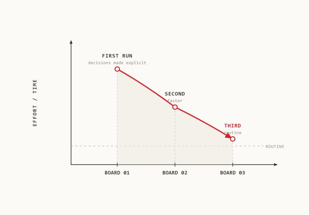
Three steps, one dataset. Each step provides input to the next, ensuring temperature is not estimated and loads are not assumed. That is the difference between three separate analyses and a single chain.

Electronics design

PCB and package in Allegro X, RF and antennas in AWR Design Environment. This is where design decisions are made.

Result: geometry, stack-up, and component placement.

Electronics Simulation

Signal and power integrity in Sigrity X, 3D electromagnetic analysis in Clarity 3D Solver, and electrothermal analysis in Celsius. The electrical design is converted into power loss and temperature.

Outcome: power loss, temperature distribution, and thermal loads.

Multiphysics system analysis

Flow and cooling in Fidelity CFD. Structural, vibration, and motion analysis in MSC Nastran, Marc, and Adams, with models built in ANSA. And the entire system operating as a digital twin.

Result: verified reliability before tooling is ordered.

disciplines

From individual physics to the complete system

Each tab represents one type of physics in your product. Start where your errors typically appear.

Signal, power, and RF

The chain begins with signals and power. Here, the electrical design translates into the power loss that every subsequent step builds upon.

Sigrity XSignal and power integrity on the actual layout
Clarity 3D Solver3D electromagnetic analysis of connectors, cables, and packages
AWR Design EnvironmentRF and antennas on the same board

Thermal and fluid dynamics

Heat is the consequence that appears first. This is where most teams identify the issue they would otherwise have encountered in the test laboratory.

Celsius EC SolverBoard, package, and enclosure in a single model
Celsius Thermal SolverTemperature in chip and package
Fidelity CFDAirflow and cooling across the complete system
Explore Celsius

Structure and vibration

Temperature turns into a mechanical load. Mechanical issues are identified before tooling is ordered — not on the shaker table.

MSC NastranDrop, shock, and vibration analysis for the complete product
MarcWarpage and non-linear stress from thermal loads
ANSA and METAPre-processing and post-processing from BETA CAE

Acoustics and noise

Noise can be calculated before it is heard, and a mechanism that holds at rest will not necessarily hold under operation.

ActranNoise from enclosure, fan, and motor
AdamsLoads across the full range of motion
Loads transferred to structureInput for Nastran and Marc

Kinematics and structural mechanics

A structure that holds at rest will not necessarily hold under operation. Loads must be calculated throughout the entire movement cycle.

AdamsMultibody dynamics simulation of mechanisms
Joints and moving partsForces across the entire motion cycle
Loads transferred to structureInput for Nastran and Marc

The entire system in operation

A virtual model of the finished system, allowing changes to be tested before equipment is relocated or added.

Cadence Reality Digital Twin PlatformData centers modeled from rack to room
Cooling under realistic operational loadAirflow and temperature while the system is operating
Changes tested virtuallyBefore they cause downtime
Martin Lange

Getting started

This does not replace your current workflow

Keep your existing CADMechanical geometry is imported from your current CAD solution. The chain starts at electrical design and ends at mechanical analysis — it does not replace either.
You start with a single linkTypically thermal: power loss from Sigrity directly into Celsius. That single link is enough to determine whether integrated analysis provides a different result than your current calculations.
A multiphysics team is not requiredThe first stage can be handled by whoever already performs the thermal assessment. A dedicated setup only becomes relevant when multiple disciplines operate together on a regular basis.

EXAMPLE

How the chain works in practice

A practical engineering workflow demonstrating how the three steps interact on a standard product.

The baseline
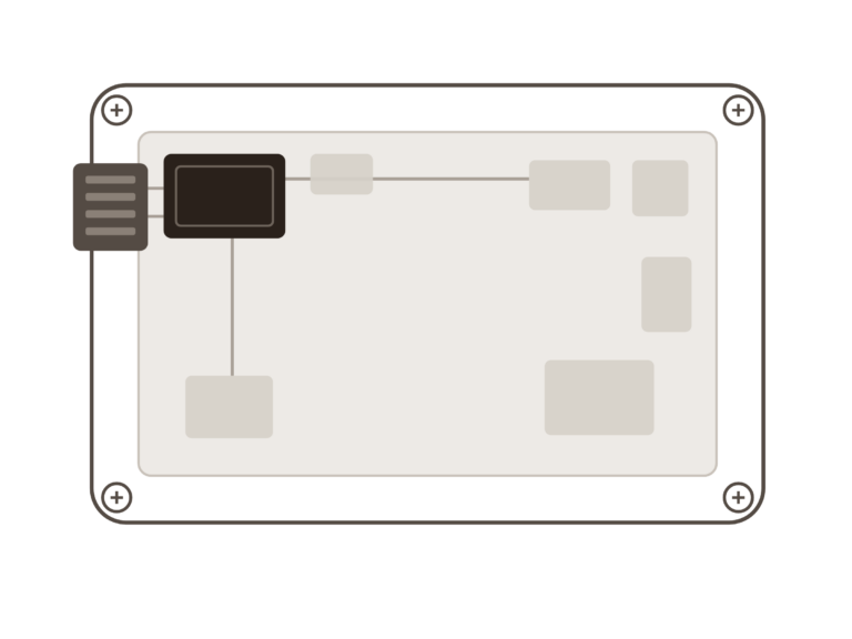
A control unit for outdoor machinery mounting. Sealed aluminum enclosure without a fan, a power module on the board, and four screws fastened directly to the machine frame. Designed for a 10-year lifespan, operating from -25 to +50 degrees Celsius.

The layout

The power module is placed close to the connector to keep traces short. Sigrity X confirms that power integrity is sound — while simultaneously providing the power loss for each component.

The temperature

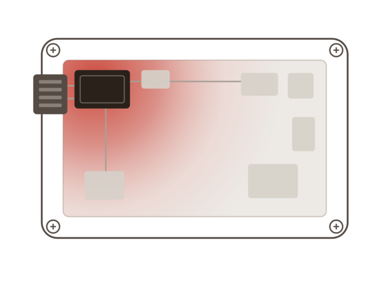
Celsius calculates the board and enclosure together. The power module stays within the datasheet limits, but with a narrow margin at 50 °C, and heat accumulates in the corner where the enclosure is fastened.

The consequence

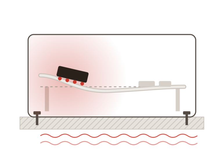
The thermal loads are transferred to the structural analysis. Daily thermal cycling causes board warpage at that exact location, and the solder joints beneath the power module are the first to suffer fatigue. Simultaneously, vibration from the machine coincides with a natural frequency in the same area.

What changed

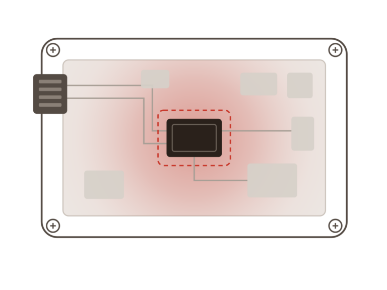
The power module is moved toward the center of the board and fitted with a thermal pad against the enclosure lid. This takes an afternoon in layout. Without the chain, the issue would typically have been caught in a thermal cycling test — after the enclosure tooling had already been ordered.

Compare

You can buy software everywhere. The difference is what comes with it.

A local partner who knows your software and your challenges makes all the difference when things get critical.

What you get NordcadStandard reseller
EDA and simulation solutions from CadenceCelsius, Sigrity X, Clarity, and Fidelity CFD consolidated with one partner.
Local hotline with real peopleYou speak with a specialist who knows your software. No ticketing systems or waiting queues.
Training and webinars in DanishOpen courses, on-site sessions, and webinars in your own language, tailored to your level.
Support for migration and setupWe assist with installation, license rehosting, and library and design migration.
Response within one business dayUrgent cases are prioritized by a human, so you rarely wait more than a few hours.
A single partner for the entire flowTools, support, and guidance in one place.

Resources

Knowledge that makes you sharper

Webinars, articles, e-books, and events on everything within electronics development.

FAQ

Frequently Asked Questions

It means that the physical consequences of an electrical design decision are calculated in context rather than in isolation. Power loss from the layout translates into temperature, temperature becomes mechanical load, and load leads to warpage or fatigue. This chain typically only becomes visible once the prototype is tested.

Likely not the tools, but how they connect. Most teams already perform thermal assessments and structural analyses — just on separate models with separate sets of assumptions. System-level design means the output of one step serves as the direct input to the next, eliminating guesswork.

Early on, while multiple design alternatives are still viable. The value decreases as more of the design is locked in — and drops to near zero once tooling is ordered. This is why we recommend starting with a single link in the chain rather than waiting for the perfect time.

Recognized by Cadence

Award-winning partnership, year after year

CADENCE
2025
Channel Partner of the Year
Latest award
CADENCE
2024
Technical Partner
Technical expertise
CADENCE
2023
Technical Partner
Technical expertise
CADENCE
2022
Pioneer Channel Partner
Early frontrunner

Contact us

Let us review your setup – without obligation.

A brief dialogue is often enough to clarify if Nordcad is the right choice for you. No pitch. No pressure.

15+ specialists