Your entire PCB flow in one tool, from schematic to 3D layout and simulation.
Try for free for 30 daysA library the design process can rely on.
PCB designFrom schematic to layout with full control.
Simulation & analysisFind the errors before the prototype does.
Thermal Simulation and AnalysisHeat accounted for from copper to enclosure.
CFD meshing & simulationThermal and flow analysis for robust designs.
RF and Antenna DesignAt high frequencies, the copper matters.
Wireless Communication & IoTRange is decided by the final millimetres.
System-Level DesignThermal and mechanical aspects calculated in time.
PLMThe current version, in one place.
Data CenterCooling determines the capacity.
Cloud ServicesComputing power when the calculation is too large.

Your entire PCB flow in one tool, from schematic to 3D layout and simulation.
Try for free for 30 daysSpecialists who work in the tools themselves.

Nordcad Customer PortalCases, licences, and downloads gathered in one place.
Software DevelopmentIntegrations and solutions that eliminate intermediate work.
MigrationFrom your legacy PCB tool to OrCAD X.
Cadence KnowledgeCadence's knowledge base with articles and guides.

Your entire PCB flow in one tool, from schematic to 3D layout and simulation.
Try for free for 30 days

Your entire PCB flow in one tool, from schematic to 3D layout and simulation.
Try for free for 30 days Clarity 3D Transient Solver

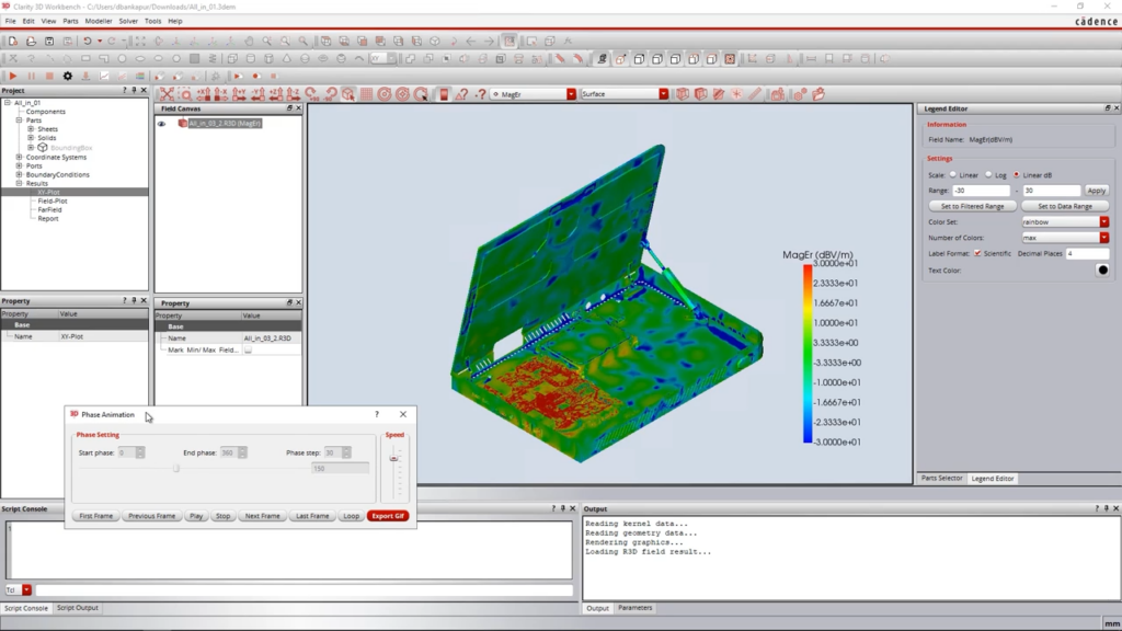
Clarity 3D Transient Solver calculates the radiated emissions from the complete product — board, cables, and enclosure in a single model. This is the analysis that reveals whether an EMC issue exists while it can still be resolved in the design.
"*" indicates required fields


The challenge
The solution

HOW IT WORKS
VALUE
Board, cables, and enclosure calculated together, enabling EMC verification during the design phase.
EMC is about the complete system, and the system is larger than the PCB.
The model must include both electronics and mechanics; otherwise, the results will not be meaningful.
What an EMC engineer needs is a clear direction, not just a number.
Simulating complete systems requires significant compute resources, and the method must keep pace.
The analysis delivers the most value before test chamber time is booked.
Implementation
Cadence delivers the solver. Nordcad helps you apply it before booking physical tests.
A product with an existing EMC test report provides the ideal baseline. This allows you to validate the simulation model against real physical measurements before relying on it for design decisions.
Determining which mechanical details matter and where simplifications can be made. These choices ensure the results remain accurate while keeping simulation times practical.
You gain direct access to specialists who understand both electronic design and EMC principles, ready to review and interpret results alongside your team.
Ready?
A brief conversation is usually enough to determine if simulation can shift your EMC verification earlier in the process. No sales pitch. No pressure. Just a practical discussion about your recent EMC testing experience.
FAQ
No. The product still needs to be tested and certified. Simulation changes when you discover whether there is a problem — and makes it possible to verify a solution without booking a new measurement slot in the lab.
That depends on the model. A result built on a well-considered model is accurate enough to identify the source and compare two solutions. That is what enables shifting the work earlier in the process.
Yes, if the question concerns radiation from the product. The enclosure and cables are often what actually radiates, and a model with only the PCB answers a different question.
3D Solver calculates the behavior of structures in the near field — the connector, vias, package. Transient Solver calculates radiation from the entire system in the far field. A product can have fine interconnections and still fail the EMC test.

Contact us
A brief dialogue is often enough to clarify if Nordcad is the right choice for you. No pitch. No pressure.


15+ specialists