
 Sigrity X PowerSI
A result you can present with confidence
PowerSI calculates the electrical behavior of the entire structure — PCB, package, or both — and extracts models that can be used downstream in simulation and presented to stakeholders.
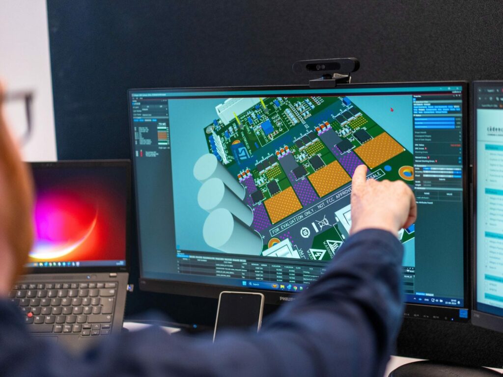
Your entire PCB flow in one tool, from schematic to 3D layout and simulation.
Try for free for 30 daysA library the design process can rely on.
PCB designFrom schematic to layout with full control.
Simulation & analysisFind the errors before the prototype does.
Thermal Simulation and AnalysisHeat accounted for from copper to enclosure.
CFD meshing & simulationThermal and flow analysis for robust designs.
RF and Antenna DesignAt high frequencies, the copper matters.
Wireless Communication & IoTRange is decided by the final millimetres.
System-Level DesignThermal and mechanical aspects calculated in time.
PLMThe current version, in one place.
Data CenterCooling determines the capacity.
Cloud ServicesComputing power when the calculation is too large.
Your entire PCB flow in one tool, from schematic to 3D layout and simulation.
Try for free for 30 daysSpecialists who work in the tools themselves.
Nordcad Customer PortalCases, licences, and downloads gathered in one place.
Software DevelopmentIntegrations and solutions that eliminate intermediate work.
MigrationFrom your legacy PCB tool to OrCAD X.
Cadence KnowledgeCadence's knowledge base with articles and guides.
Your entire PCB flow in one tool, from schematic to 3D layout and simulation.
Try for free for 30 daysYour entire PCB flow in one tool, from schematic to 3D layout and simulation.
Try for free for 30 days Sigrity X PowerSI
PowerSI calculates the electrical behavior of the entire structure — PCB, package, or both — and extracts models that can be used downstream in simulation and presented to stakeholders.
"*" indicates required fields
The challenge
The solution
HOW IT WORKS
Traces, planes, vias, and stackup are calculated exactly as designed. It is the structural details that determine performance at high frequencies.
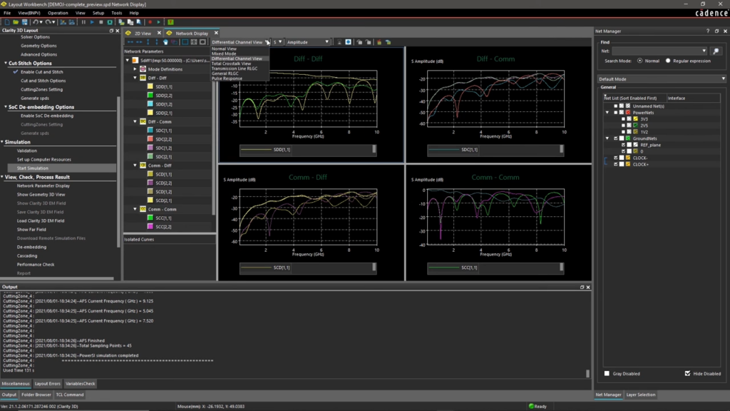
The result is not just a colored plot, but extracted models — typically S-parameters — that can be used directly in further simulations.
Design data can come from Allegro X or other ECAD tools, including formats like IPC-2581 and ODB++.
VALUE
From impedance and coupling to extracted models, across both PCB and package.
The question is rarely whether a trace conducts current. It is how the structure behaves at the frequencies actually present in the signal.
The transition between package and board is often where analyses fall short.
An analysis that cannot be used downstream remains just an image in a report.
The tool must read the design you have, without requiring a specific format.
PowerSI is the tool to use when you need reliable answers, not just rough indications.
Implementation
Start with a design you have already measured. That allows you to validate the model against real-world data before using it to make decisions.
Determining the required frequency range, what to include in the model, and what can be omitted. These decisions directly affect both simulation time and accuracy.
You get direct access to specialists who run these analyses themselves and can discuss specific results with you.
Ready?
A short conversation is usually enough to clarify whether PowerSI covers the requirements you need to document. No pitch. No pressure. Just an open discussion about the interfaces causing challenges.
FAQ
Aurora runs directly within the layout environment and provides fast feedback during design. PowerSI is the tool used when results must be thoroughly verified and documented, and when models need to be extracted for further simulation. Many teams use both.
Yes. PowerSI imports design data from other ECAD tools, including IPC-2581 and ODB++ formats.
Yes, the electrical domain: impedance and resonances in the power distribution network. If decoupling capacitor optimization is required, OptimizePI is the appropriate solution, and if the power distribution network spans across multiple boards, SystemPI is used. For thermal co-analysis, Celsius PowerDC is applied.
When the focus shifts from the physical structure to the full channel: eye diagrams, drivers and receivers, and high-speed serial links. In those cases, Advanced SI is used, with PowerSI typically supplying the structural model for that analysis.

Contact us
A brief dialogue is often enough to clarify if Nordcad is the right choice for you. No pitch. No pressure.


 15+ specialists