Your entire PCB flow in one tool, from schematic to 3D layout and simulation.
Try for free for 30 daysA library the design process can rely on.
PCB designFrom schematic to layout with full control.
Simulation & analysisFind the errors before the prototype does.
Thermal Simulation and AnalysisHeat accounted for from copper to enclosure.
CFD meshing & simulationThermal and flow analysis for robust designs.
RF and Antenna DesignAt high frequencies, the copper matters.
Wireless Communication & IoTRange is decided by the final millimetres.
System-Level DesignThermal and mechanical aspects calculated in time.
PLMThe current version, in one place.
Data CenterCooling determines the capacity.
Cloud ServicesComputing power when the calculation is too large.

Your entire PCB flow in one tool, from schematic to 3D layout and simulation.
Try for free for 30 daysSpecialists who work in the tools themselves.

Nordcad Customer PortalCases, licences, and downloads gathered in one place.
Software DevelopmentIntegrations and solutions that eliminate intermediate work.
MigrationFrom your legacy PCB tool to OrCAD X.
Cadence KnowledgeCadence's knowledge base with articles and guides.

Your entire PCB flow in one tool, from schematic to 3D layout and simulation.
Try for free for 30 days

Your entire PCB flow in one tool, from schematic to 3D layout and simulation.
Try for free for 30 days Visual System Simulator

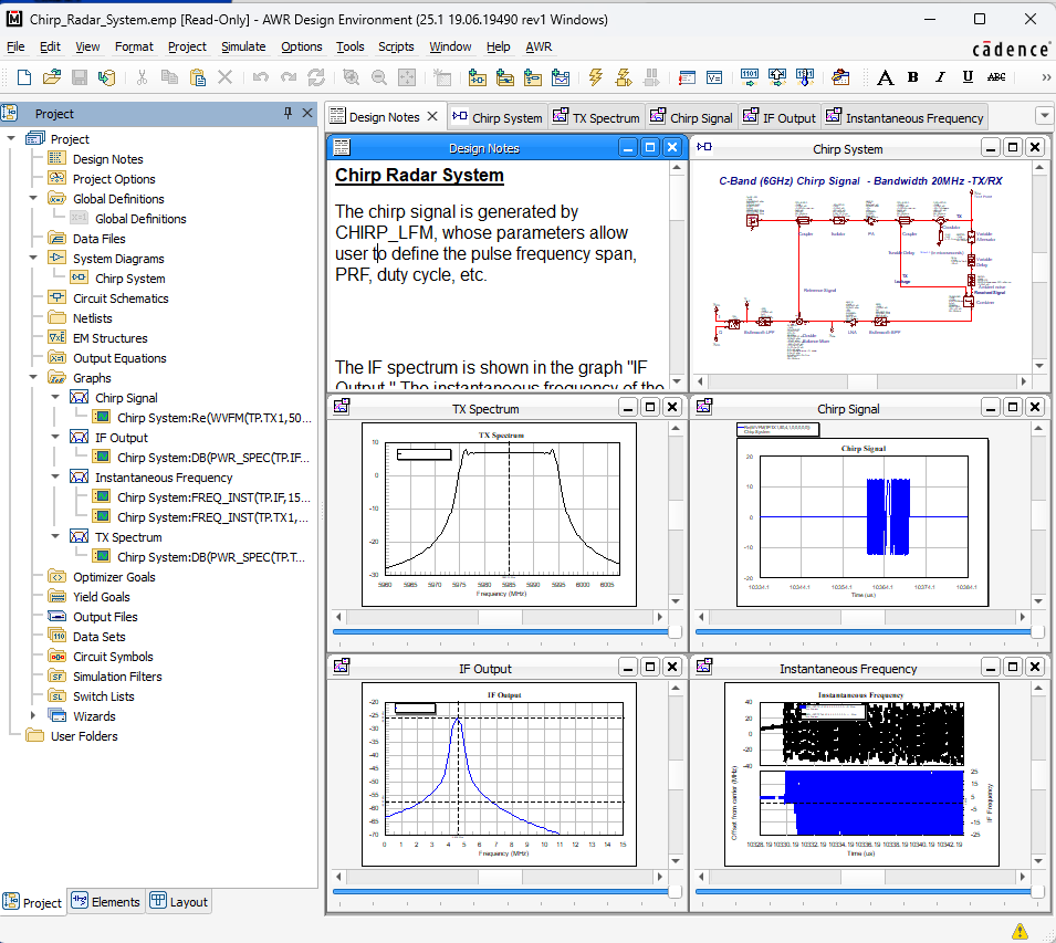
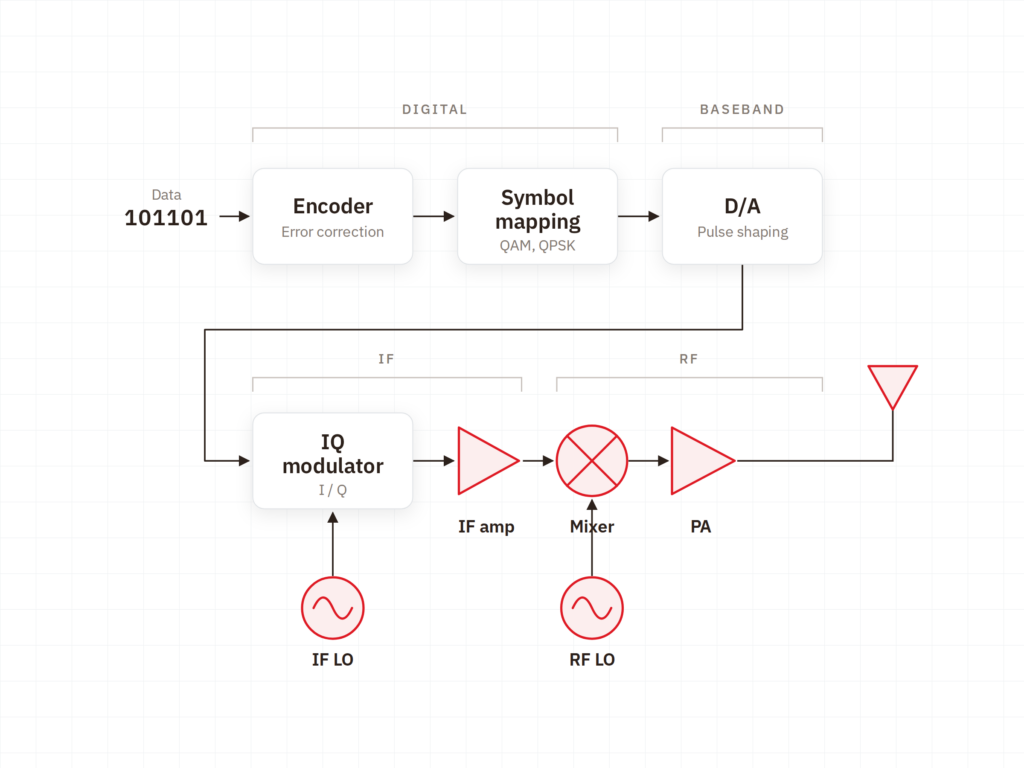
VSS simulates the complete RF system at architecture level, showing you what each block must deliver for the whole to work. It is more cost-effective to adjust a requirement here than to fix it in an amplifier design later.
"*" indicates required fields


The challenge
The solution

HOW IT WORKS
VALUE
Architecture, requirements, and performance calculated for the whole — with the option to import actual circuits along the way.
The primary question is not how to build the block, but what it needs to deliver.

A system must be calculable in both time and frequency domains, depending on the question.

The system is evaluated on the metrics referenced by customers and standards.

The value lies in switching between levels without rebuilding the model.

System simulation is used where the chain is long and requirements are defined externally.

Implementation
Cadence provides the tool. Nordcad helps you apply it to early design decisions.
An existing solution is the simplest starting point. It allows the model to be verified against physical measurements.
A system model must be high-level enough to iterate quickly and precise enough to be useful. We help you find that balance.
You gain access to specialists who work with RF from system to circuit level, capable of supporting decisions at both stages.
Ready?
A brief conversation is usually enough to clarify whether system-level modeling addresses your uncertainties. No pitch. No pressure. Just a straightforward technical discussion about your signal chain.
FAQ
When the chain is long enough that the critical block is not obvious — and when requirements are dictated externally by a standard. For a single amplifier stage, Microwave Office is sufficient.
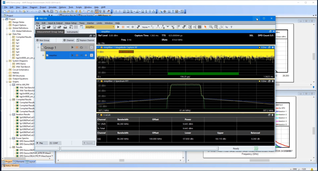
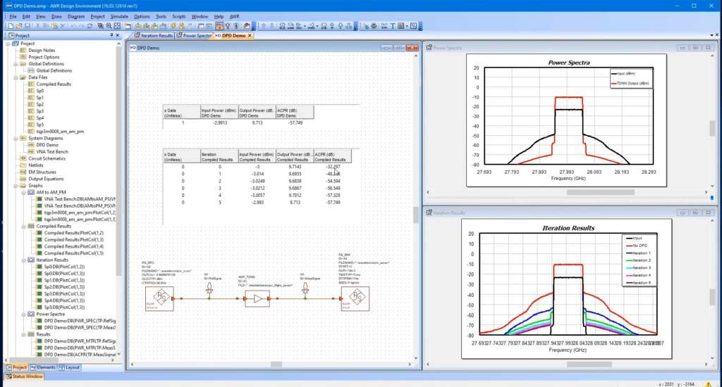
Yes. A block can be replaced with the actual design from Microwave Office, allowing the system to run with real-world behavior instead of an idealized model.
Accurate enough to rank order. The purpose is to determine where requirements should be set and where the bottleneck lies — not to predict the final tenth of a dB.
They are designed in Microwave Office, and the structures are verified in AXIEM or Analyst. VSS is the level above, and the four tools are typically used in that sequence.

Contact us
A brief dialogue is often enough to clarify if Nordcad is the right choice for you. No pitch. No pressure.


15+ specialists