OrCAD X

Your entire PCB flow in one tool, from schematic to 3D layout and simulation.

Try for free for 30 days

Try the tools Contact us

Clarity 3D Solver

The connector is also part of the circuit

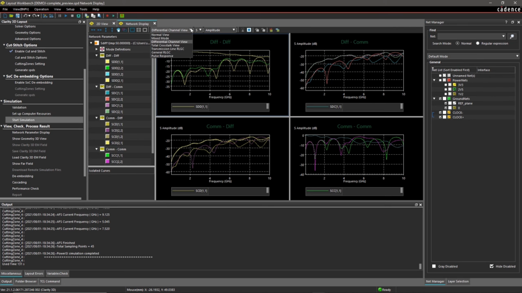
Clarity 3D Solver calculates the electromagnetic behavior of the physical structures the signal passes through: connectors, cables, vias, packages, and transitions. The result is a model ready for further signal analysis.

3,600+ installations throughout the Nordics

The challenge

It costs you time and money

  • The connector is factored into the simulation as an estimate
  • The transition between package and board is not included in the calculation
  • The model from the vendor does not cover your setup
  • Support responses that take days

The solution

We give you control back

  • The structure calculated on the actual geometry
  • Transitions between layers, package, and board included in the model
  • A model you can build yourself, rather than one you have to request
  • Local hotline with responses from a specialist on the same day
Martin LangeHead of Support & Service

HOW IT WORKS

From physical structure to usable model

The geometry is the starting pointWhere there is no layout to read — a connector, a cable, a transition — the geometry determines the result. It is calculated as it is.
The result is S-parametersThe analysis does not end in an image, but in a model of the structure that integrates into the subsequent signal analysis alongside the rest of the channel.
Built to scaleThe solver distributes the computation across multiple cores, making it possible to calculate structures that would otherwise be too large.

VALUE

Clarity 3D Solver covers the structures the signal must pass through

From connector and cable to via, package, and transition — calculated in three dimensions and delivered as a model.

What it calculates

The places where the signal changes media are also the places where it suffers loss.

Connectors and cablesWhat is not drawn in ECAD
Vias and layer transitionsWhere the channel changes planes
Packages and SiPThe transition between chip and board
Explore

The method

3D frequency-domain analysis is the method when the question is how a structure behaves.

Finite element methodArbitrary 3D geometry
Distributed computingMultiple cores on the same task
Large structuresEven those that are otherwise too demanding
Explore

Into signal analysis

An EM model only provides value when used alongside the rest of the channel.

S-parameters for the structureThe model of the physical part
Used together with Sigrity XThe entire channel calculated as one
Comparison of variantsTwo connectors compared against each other
Explore

In the design flow

The analysis must be able to run directly on the design you are working on.

Allegro and SiP LayoutBoard and package data
VirtuosoFrom the chip side
Mechanical geometryWhat does not exist in ECAD
Explore

Implementation

How Clarity 3D Solver works in practice

Cadence provides the solver. Nordcad helps you apply it to the structures that define your design.

Start with the structure you are most uncertain about

Typically a connector or a transition where you currently rely on a vendor model or an estimate. This also provides the best basis for comparison.

Guidance on modeling and boundary setup

Where to set the boundaries for the model, and how finely the structure should be meshed. These are the choices that determine both computation time and accuracy.

Local expertise and ongoing support

You gain access to specialists who work with signal integrity daily and can review a result together with you.

Ready?

Ready to design with peace of mind?

A brief conversation is usually enough to clarify whether 3D analysis is necessary for your structures. No pitch. No pressure. Just an open discussion about where your channel models stop matching reality.

FAQ

Frequently Asked Questions

Often you can, and it is a solid starting point. However, the model applies to the vendor's setup, not necessarily your stackup, your routing, or your mounting method. That is where the difference between the model and reality arises.

Sigrity X calculates what is drawn in ECAD: traces, planes, and vias. Clarity calculates the physical 3D structure — including the connector and the cable, which do not exist in the layout. They are typically used together, with Clarity delivering the structural model into the channel analysis.

The computation is distributed across multiple cores, which is what determines practical limits. The cloud version makes it possible to access compute power for an individual demanding task without investing in hardware.

No. 3D Solver calculates the structure's behavior in the frequency domain — the near field. Transient Solver is built for radiation from the entire system — the far field. They each address distinct questions.

Contact us

Let us review your setup – without obligation.

A brief dialogue is often enough to clarify if Nordcad is the right choice for you. No pitch. No pressure.

15+ specialists