Your entire PCB flow in one tool, from schematic to 3D layout and simulation.
Try for free for 30 daysA library the design process can rely on.
PCB designFrom schematic to layout with full control.
Simulation & analysisFind the errors before the prototype does.
Thermal Simulation and AnalysisHeat accounted for from copper to enclosure.
CFD meshing & simulationThermal and flow analysis for robust designs.
RF and Antenna DesignAt high frequencies, the copper matters.
Wireless Communication & IoTRange is decided by the final millimetres.
System-Level DesignThermal and mechanical aspects calculated in time.
PLMThe current version, in one place.
Data CenterCooling determines the capacity.
Cloud ServicesComputing power when the calculation is too large.

Your entire PCB flow in one tool, from schematic to 3D layout and simulation.
Try for free for 30 daysSpecialists who work in the tools themselves.

Nordcad Customer PortalCases, licences, and downloads gathered in one place.
Software DevelopmentIntegrations and solutions that eliminate intermediate work.
MigrationFrom your legacy PCB tool to OrCAD X.
Cadence KnowledgeCadence's knowledge base with articles and guides.

Your entire PCB flow in one tool, from schematic to 3D layout and simulation.
Try for free for 30 days

Your entire PCB flow in one tool, from schematic to 3D layout and simulation.
Try for free for 30 days Analyst

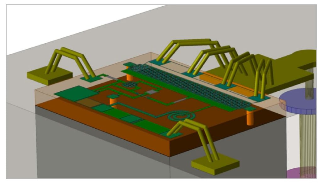
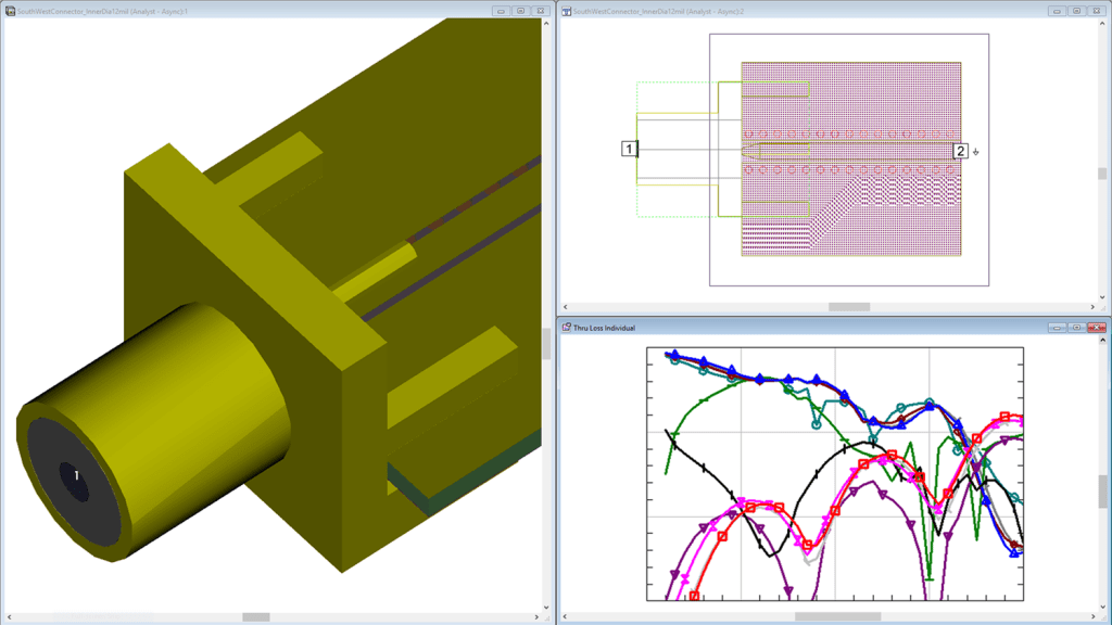
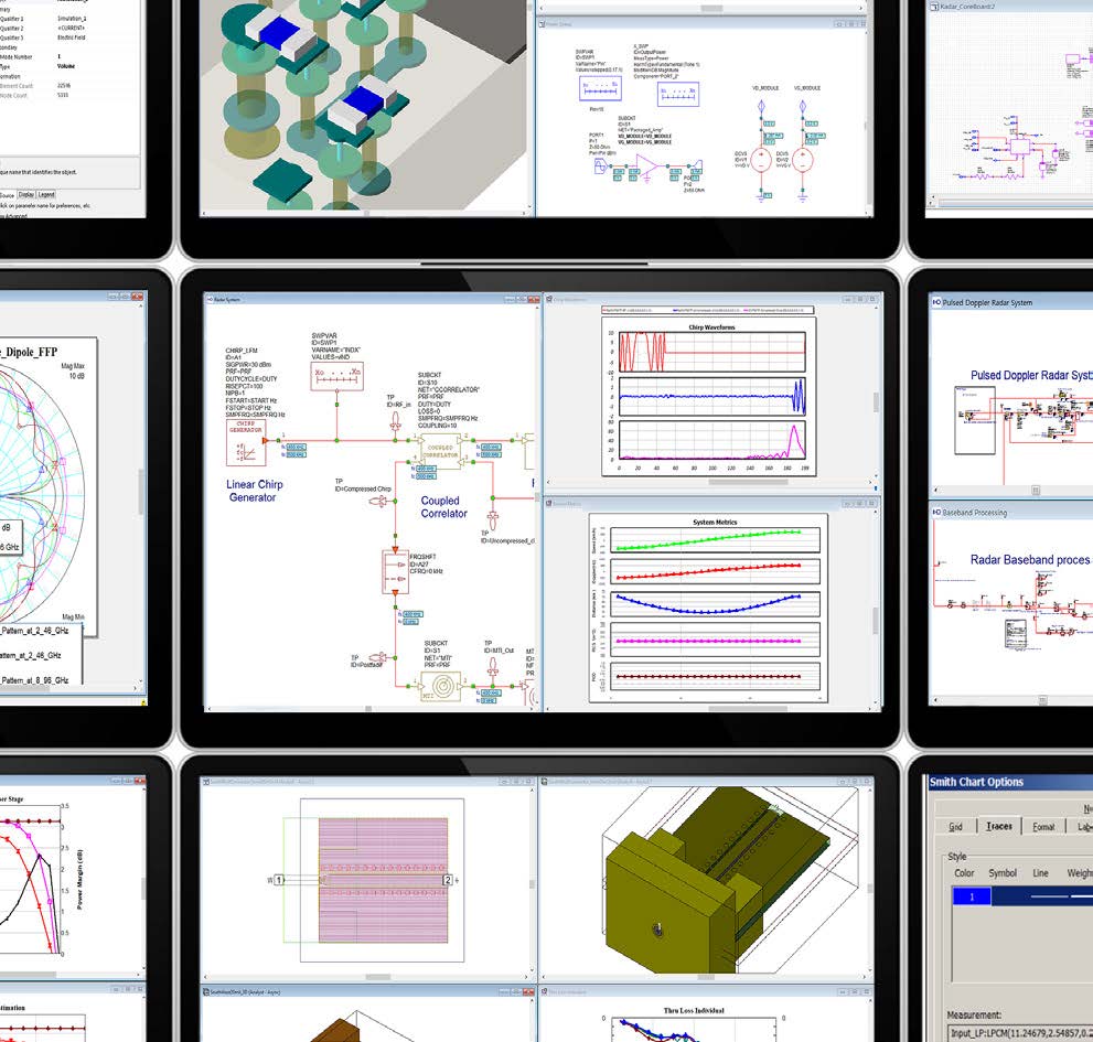
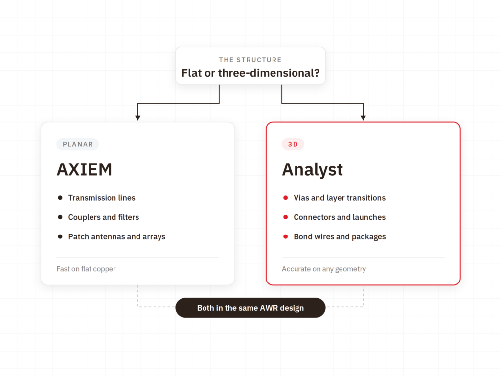
Analyst provides 3D EM analysis using the finite element method. It calculates the structures a planar solver cannot handle: transitions, connectors, enclosures, and true 3D components within the RF design.
"*" indicates required fields


The challenge
The solution

HOW IT WORKS
VALUE
Transitions, connectors, and 3D components, calculated in the same environment as the rest of the RF design.
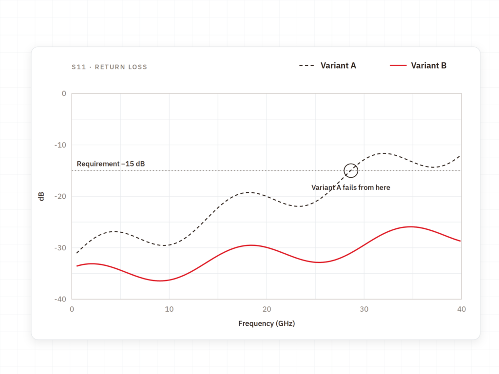
What causes issues at high frequencies is rarely the transmission line. It is the transition.

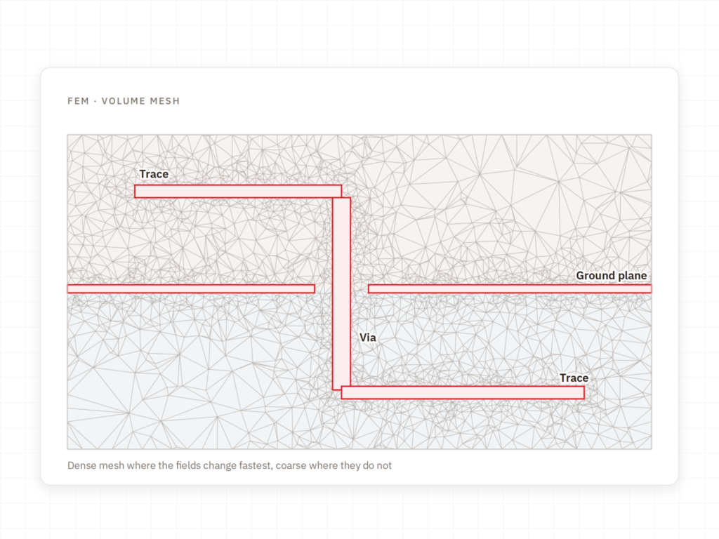
FEM is chosen because it places no constraints on the shape of the geometry.

A 3D analysis must be directly usable by the engineer working on the circuit.

The tool resides within the design environment, and that makes all the difference.

3D analysis requires compute time, so it should be used where it delivers clear value.

Implementation
Cadence delivers the solver. Nordcad helps you apply it where it provides value.
A 3D analysis of everything is neither necessary nor practical. We provide guidance on which transitions are worth calculating.
How fine the mesh should be, and where the model boundaries should be set. These choices determine both simulation time and reliability.
You gain access to specialists who run 3D EM in practice and can assess whether a result is dependable.
Ready?
A brief conversation is usually enough to clarify whether you need 3D analysis or if AXIEM is sufficient. No pitch. No pressure. Just a direct technical discussion about the structures causing issues.
FAQ
When the geometry has a true third dimension. As long as the structure is planar — lines, couplers, patch antennas — AXIEM is both faster and sufficient. A connector, a transition between layers, or an enclosure requires Analyst.
Both are 3D EM solvers. Analyst is part of the RF flow in AWR and is used alongside circuit design. Clarity belongs to the electronics simulation portfolio and is typically used for interconnects, packages, and connectors in digital designs. The choice usually depends on the design environment you work in, rather than the geometry alone.
It depends entirely on the size of the structure and the required mesh resolution. That is why guidance on what to include in the model is just as important as the tool itself.
In practice, Analyst is used on structures directly from a Microwave Office design. If you have a different workflow in mind, we review it together before you make any decisions.

Contact us
A brief dialogue is often enough to clarify if Nordcad is the right choice for you. No pitch. No pressure.


15+ specialists