Your entire PCB flow in one tool, from schematic to 3D layout and simulation.
Try for free for 30 daysA library the design process can rely on.
PCB designFrom schematic to layout with full control.
Simulation & analysisFind the errors before the prototype does.
Thermal Simulation and AnalysisHeat accounted for from copper to enclosure.
CFD meshing & simulationThermal and flow analysis for robust designs.
RF and Antenna DesignAt high frequencies, the copper matters.
Wireless Communication & IoTRange is decided by the final millimetres.
System-Level DesignThermal and mechanical aspects calculated in time.
PLMThe current version, in one place.
Data CenterCooling determines the capacity.
Cloud ServicesComputing power when the calculation is too large.

Your entire PCB flow in one tool, from schematic to 3D layout and simulation.
Try for free for 30 daysSpecialists who work in the tools themselves.

Nordcad Customer PortalCases, licences, and downloads gathered in one place.
Software DevelopmentIntegrations and solutions that eliminate intermediate work.
MigrationFrom your legacy PCB tool to OrCAD X.
Cadence KnowledgeCadence's knowledge base with articles and guides.

Your entire PCB flow in one tool, from schematic to 3D layout and simulation.
Try for free for 30 days

Your entire PCB flow in one tool, from schematic to 3D layout and simulation.
Try for free for 30 days Microwave Office

Microwave Office is the core of AWR. Schematic and layout are connected throughout the design, and harmonic balance provides clear answers on how the circuit behaves at the actual signal levels it operates at.
"*" indicates required fields


The challenge
The solution

HOW IT WORKS
VALUE
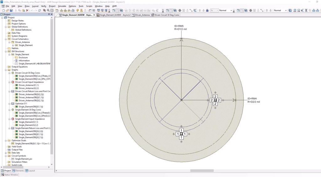
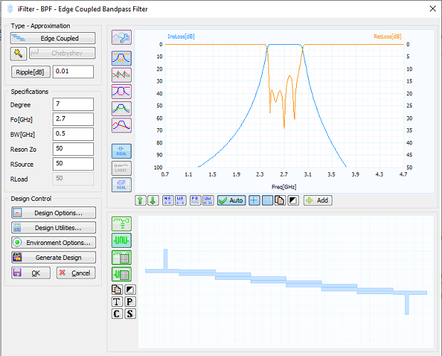
Linear and non-linear simulation, amplifier design, synchronized layout, and EM analysis in a single environment.
RF circuits must be calculated both linearly and at the power levels where they cease to be linear.

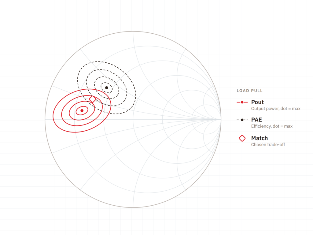
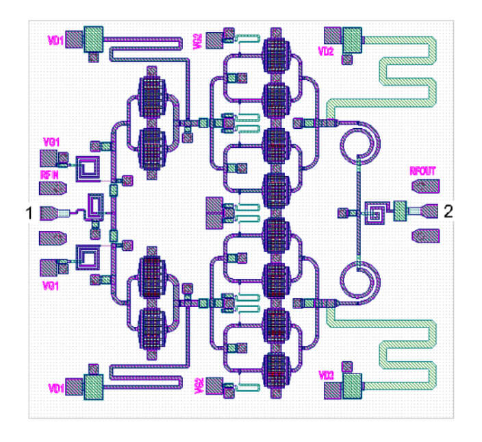
The power amplifier is the task that determines whether an RF design meets its specification.

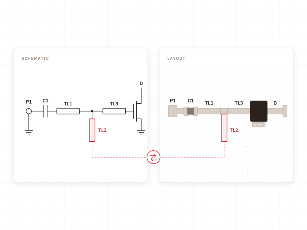
In RF, geometry is part of the circuit, meaning the two must stay synchronized.

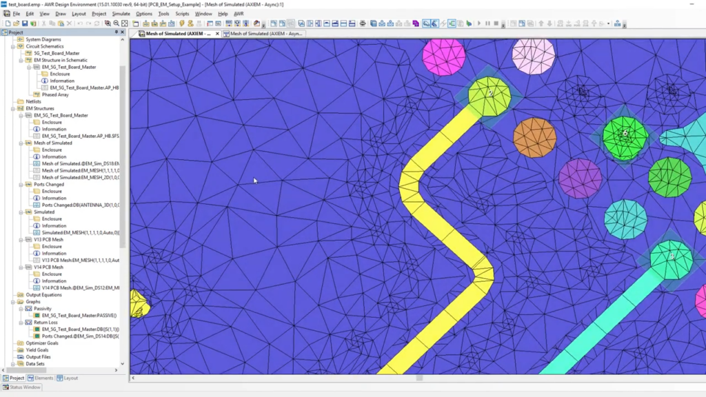
Electromagnetic analysis provides the greatest value when run continuously rather than at the very end.

The same circuit is implemented differently depending on the chosen technology.

Implementation
Cadence provides the software. Nordcad helps you adapt it to your specific technology.
An RF design is tied to the process or substrate it is built on. We help you set up this foundation correctly, as everything else builds upon it.
Not everything requires EM analysis, and excessive analysis consumes time. We advise on which structures are worth simulating and at which stages in the flow.
You gain direct access to specialists who work with RF daily and can discuss any unexpected results with you.
Ready?
A brief conversation is usually enough to clarify whether Microwave Office alone covers your needs. No sales pitch. No pressure. Just an open dialogue about your operating frequencies and technologies.
FAQ
Often, yes. Most teams start here, as the core circuit design happens within this tool. EM tools become relevant when physical geometry drives the result, and VSS when system architecture must be defined.
It depends on the foundry. AWR is widely used for MMIC design with foundry process design kits (PDKs), and we verify your specific setup before anything is agreed upon.
Yes. The RF circuit is designed in AWR and can be transferred seamlessly into the PCB flow in Allegro. How much data needs to be exchanged depends on whether the RF section is on its own board or part of a larger PCB.
That is handled in Celsius. An amplifier designed to meet its specifications can still overheat — and that analysis is addressed elsewhere in the portfolio.

Contact us
A brief dialogue is often enough to clarify if Nordcad is the right choice for you. No pitch. No pressure.


15+ specialists